Session 7: Building the CE Expanding Bag Digester#
Introduction#
This session is the practical step-by-step guide to constructing the CREATIVenergie Expanding Bag Digester. Work through each step carefully and refer to the sizing tables from Session 2 to confirm your dimensions before you begin.
Note
Three standard sizes are available: 5 m³, 8 m³, and 13 m³. Downloadable CAD drawings for each size are available on the CREATIVenergie website.
Case Study: Overview of a Working Digester#
Sanile gives an overview of how a completed CREATIVenergie digester looks and works.
Case Study: Uses of Biogas Demo#
Tools and Materials Checklist#
Before starting, confirm you have:
Sizing table for your chosen digester size
CAD drawing for your size
String line and posts (for reference line)
Tape measure
Spade and pick
Cement, sand, and aggregate (for base)
Bricks and mortar (for inlet and outlet chambers)
Pond liner / digester bag
PVC gas pipe, valves, and fittings
Inlet and outlet covers (hinged to prevent wind damage)
Steel wool (for H₂S filter — replace monthly)
Bubbler
Rock salt or caustic soda solution (if tree roots present)
Step-by-Step Construction#
Step 1: Set Up the Reference Line#
Establish a horizontal reference line across the site using posts and string. All depth measurements during construction will be taken from this line.
Tip
The reference line is your single most important measurement tool. Set it level and keep it in place throughout the build.
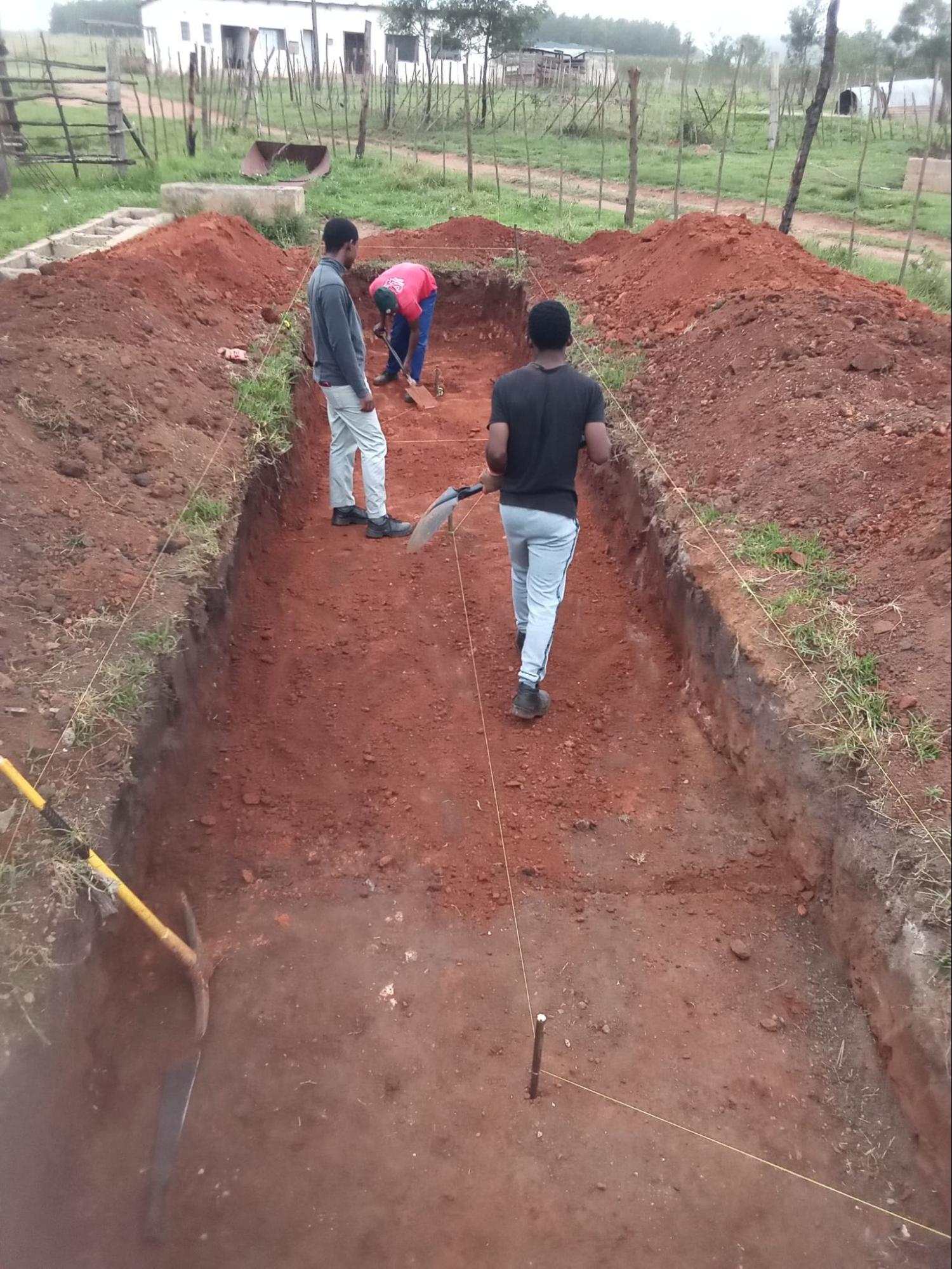
Fig. 19 Step 1 in the field: string line and posts marking the horizontal datum for all subsequent depth measurements.#
Step 2: Mark the Excavation Area#
Using the reference line and your CAD drawing, mark out the full footprint of the pit, inlet, and outlet positions on the ground.
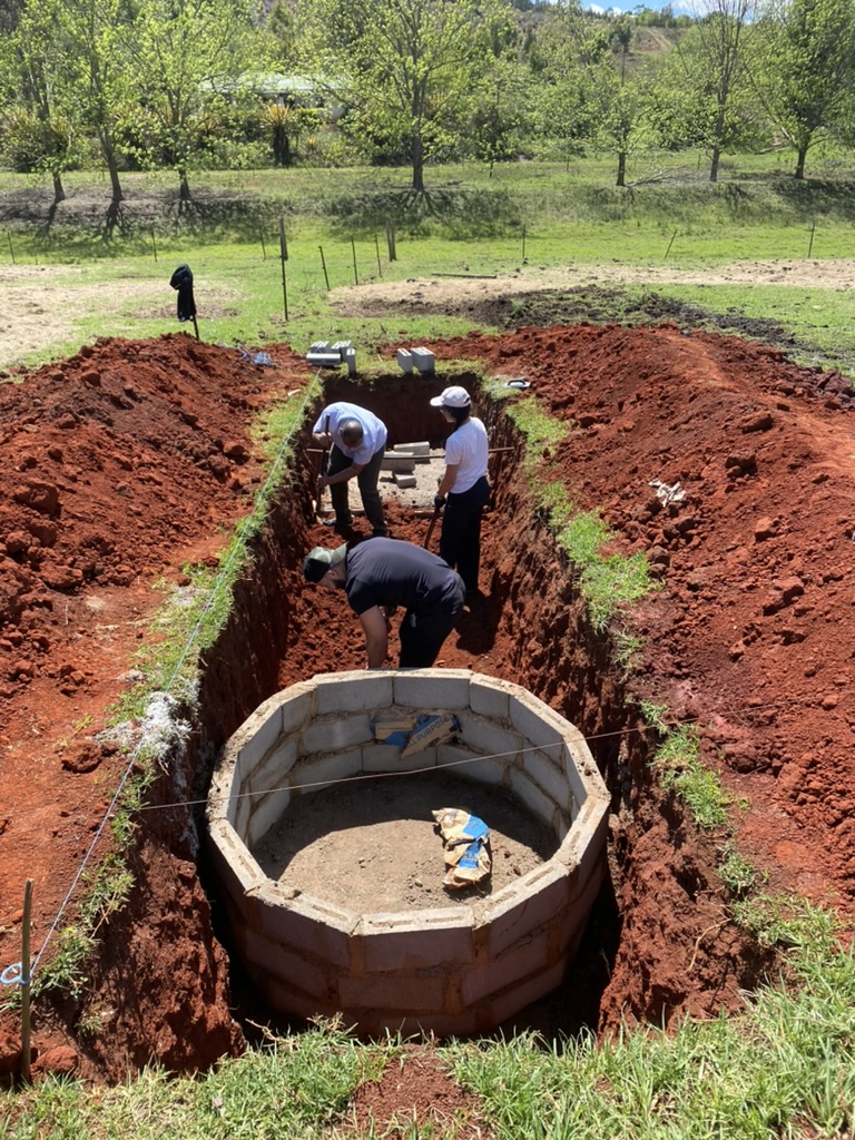
Fig. 20 Step 2: The full pit footprint marked on the ground before excavation begins.#
Step 3: Dig the Pit#
Excavate the pit to the dimensions specified in your sizing table. Use the reference line to check depth at multiple points.
Remove all roots from the sides and base of the pit.
If roots are present nearby, apply rock salt or caustic soda solution and allow to dry before proceeding.
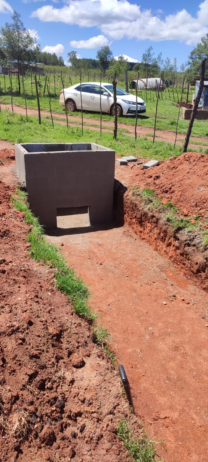
Fig. 21 Step 3 complete: a clean, root-free excavated pit ready for the concrete base.#
Step 4: Lay the Concrete Base#
Pour and level a concrete base for the inlet and outlet chambers. Allow to cure fully before building brickwork on top.
Use the reference line to verify that the base level matches your drawing.
Step 5: Build the Brick Inlet and Outlet Chambers#
Construct the inlet and outlet chambers in brick up to the specified height. Include the throat bricks that keep slurry level correct relative to gas pressure.
Key dimensions to verify against your drawing:
Height of outlet (Ho) — must be below the gas pipe outlet height
Height of inlet (Hi) — must be higher than Ho to ensure slurry flows from inlet to outlet
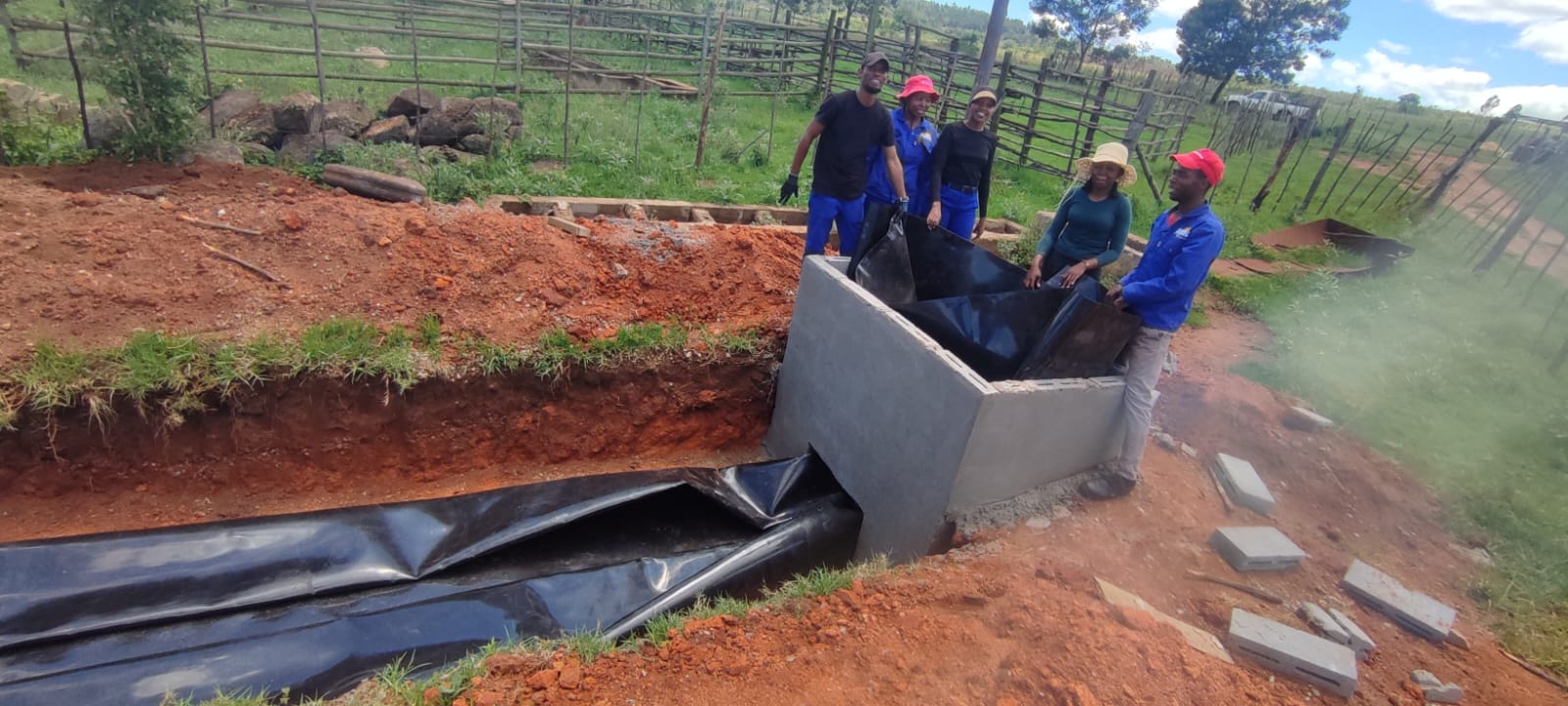
Fig. 22 Step 5a: Building the brick inlet chamber — throat bricks visible at the correct height.#
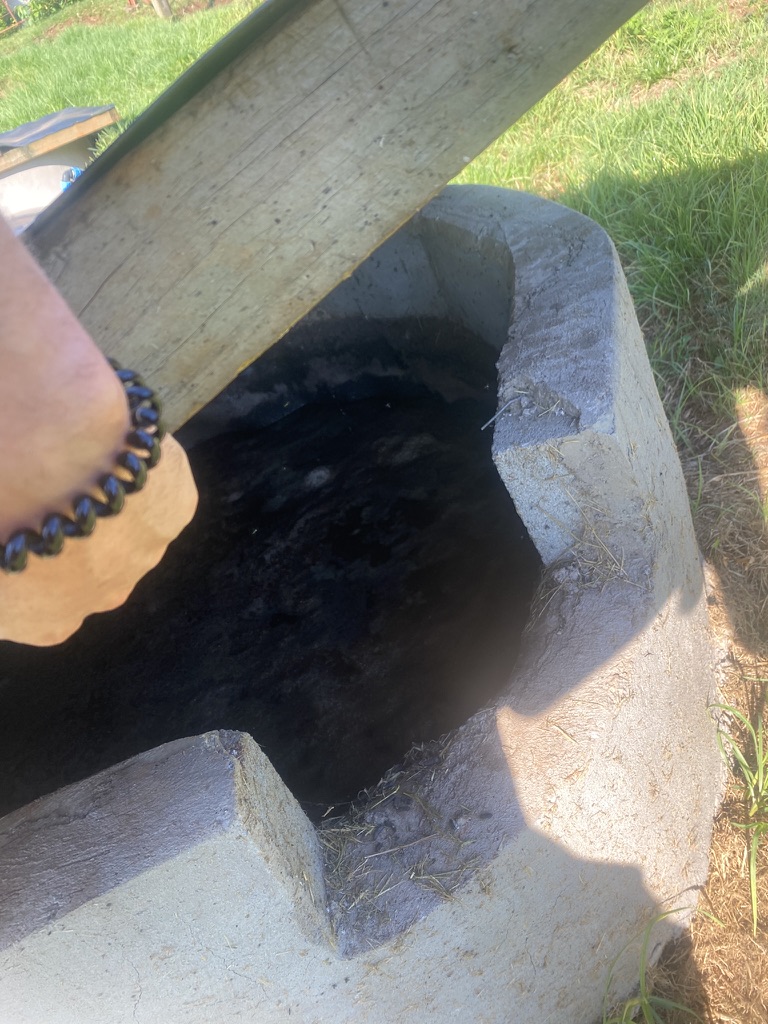
Fig. 23 Step 5b: Completed outlet chamber showing the finished brickwork and outlet opening.#
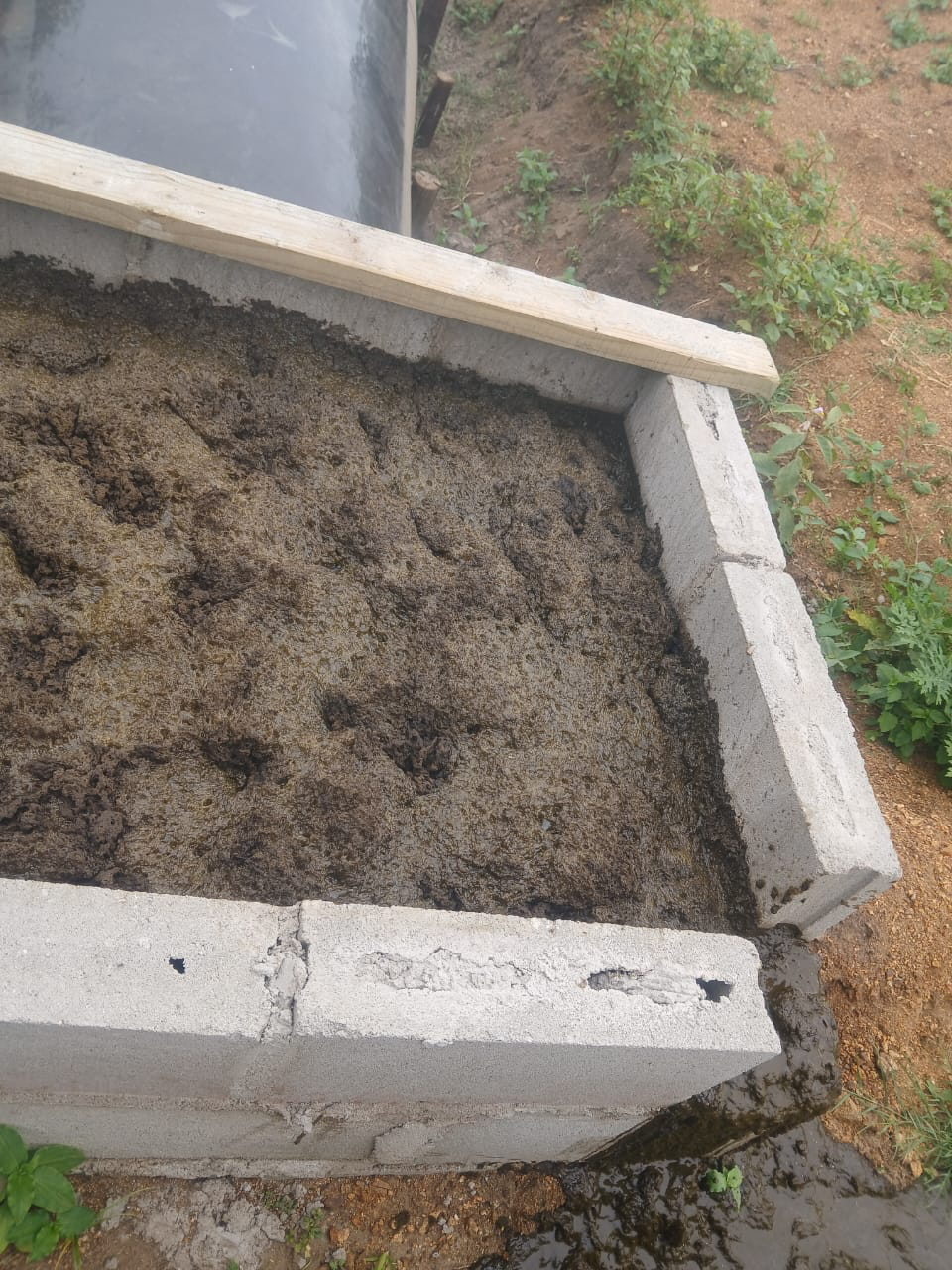
Fig. 24 Inlet height (Hi) must always be higher than outlet height (Ho) to ensure gravity-driven slurry flow.#
Step 6: Cut and Glue the Bag Sheet#
Cut the pond liner/bag material to the dimensions specified for your digester size. Glue seams according to the manufacturer’s instructions, ensuring a completely airtight seal.
Warning
Test the bag for leaks by inflating gently before installation. Any leaks must be sealed before the bag goes in the ground.
Note
You practised this test back in Session 1 — close the valve, inflate gently, brush soapy water over every seam, and watch for bubbles. If you want a reminder, the interactive simulation is in Session 1: Principles of Biogas.
Step 7: Insert the Bag#
Lower the sealed bag into the pit. Connect the inlet and outlet fittings, ensuring all connections are airtight.
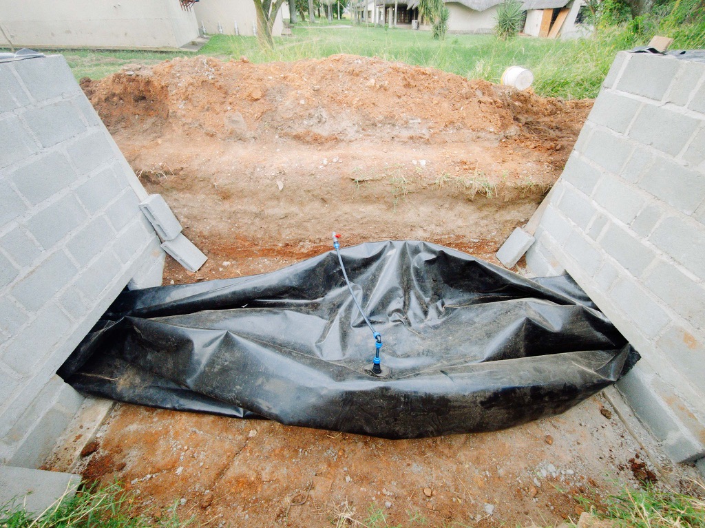
Fig. 25 Step 7a: The bag is carefully lowered into the pit before the inlet and outlet fittings are connected.#
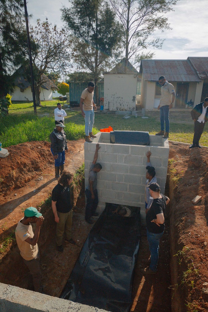
Fig. 26 Step 7b: Bag in position with fittings connected — all joints checked for airtightness before backfilling.#
Step 8: Make Covers for Inlet and Outlet#
Construct covers for the inlet and outlet openings. Attach each cover to the brickwork with a hinge to prevent it from blowing away and damaging the digester bag.
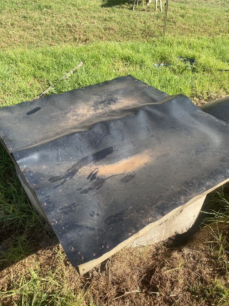
Fig. 27 Step 8a: Hinged inlet cover — the hinge prevents wind from carrying the cover away and puncturing the bag.#
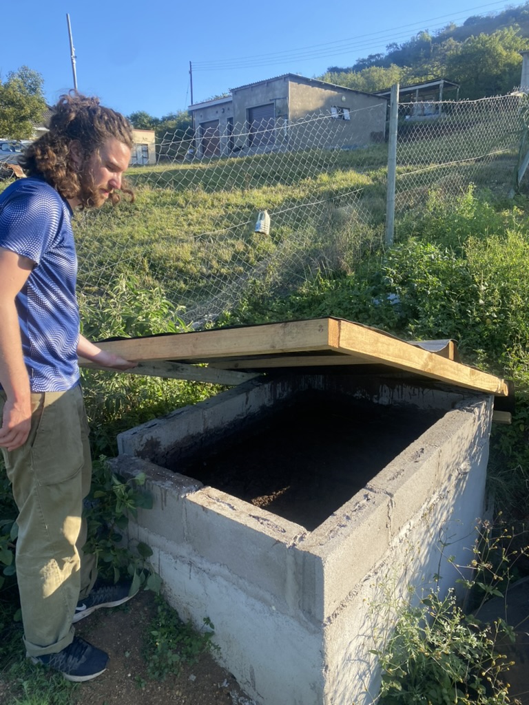
Fig. 28 Step 8b: Outlet cover secured with a hinge. Both covers should open easily for daily feeding and checking.#
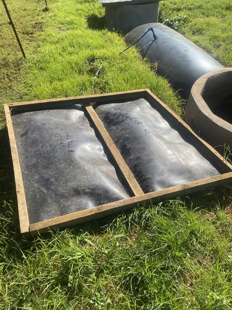
Fig. 29 Step 8 complete: both covers fitted and hinged, and the surface around the digester tidied.#
Step 9: Connect the Pipework#
Run PVC gas pipe from the bag to the point of use (kitchen, stove).
Install the bubbler in the gas line as a flashback preventer.
Install the steel wool H₂S filter after the bubbler.
Install a ball valve at the point where the pipe enters the house.
Install the main shutoff valve near the digester.
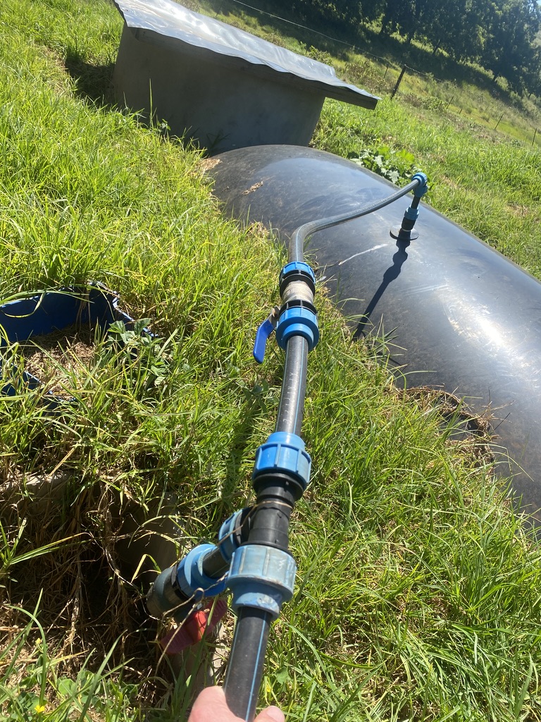
Fig. 30 Step 9a: Gas pipe run from the digester — bubbler (flashback preventer) and steel wool H₂S filter installed in sequence.#
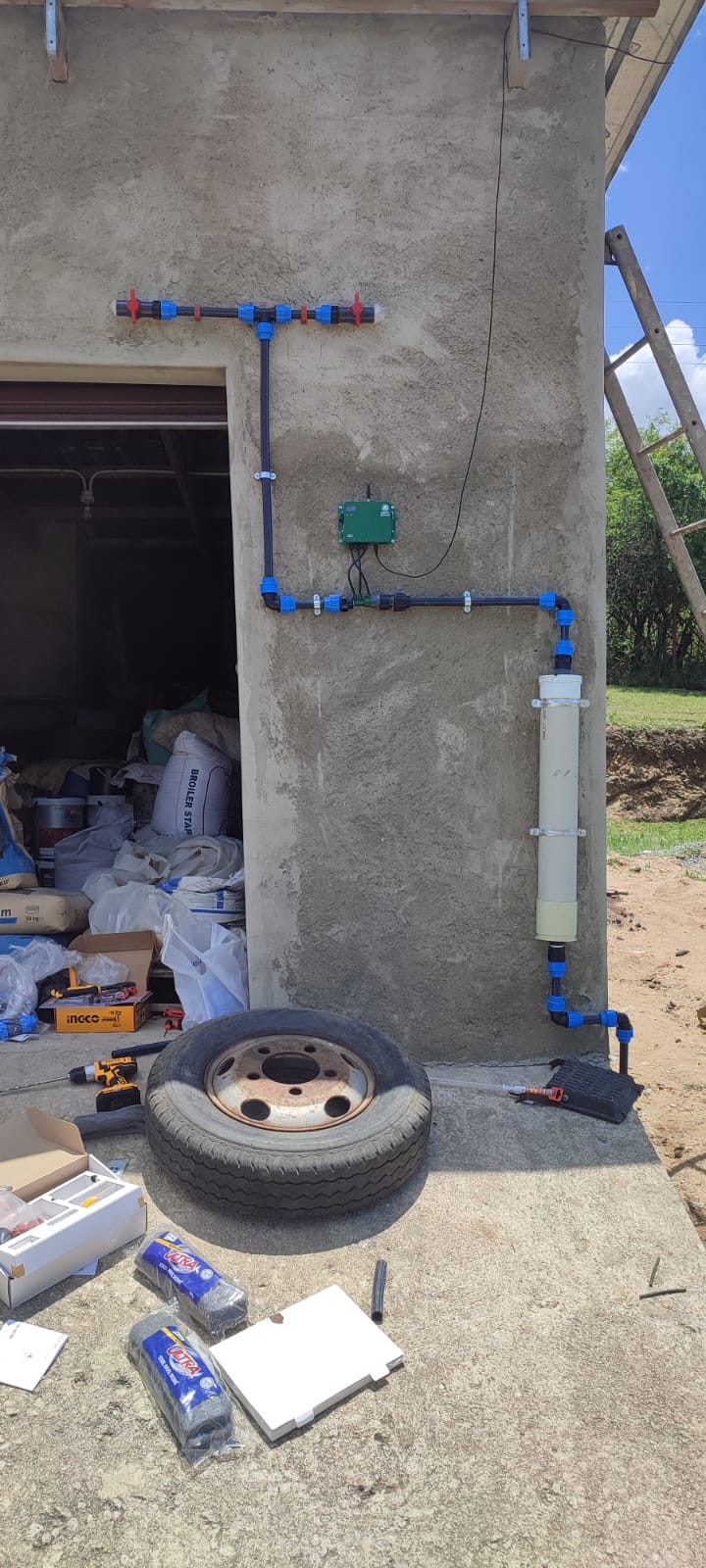
Fig. 31 Step 9b: Main shutoff valve near the digester and ball valve at the house entry — two independent control points for safe operation.#
Step 10: First Fill#
Mix feedstock (e.g. cow dung) with water at a 1:1 ratio and fill the digester to the correct starting level.
The first gas production typically takes 2–4 weeks as the microbial population establishes.
Do not use the gas for the first week — vent it. The first gas produced contains mostly CO₂, which will not burn well. Proper methane-rich gas follows.
Checking Your Work#
Before declaring the build complete, run through the full QA checklist below. All items must be ticked before the system is handed over.
✅ Build QA Checklist — tick each item to sign off
Session 7 Quiz#
True / False Q1. The reference line set up at the start of construction is used for all depth measurements throughout the build.
MC Q2. Which is correct regarding inlet height (Hi) and outlet height (Ho)?
Fill in Q3. Before the bag is lowered into the pit, it must be tested for ___ by inflating it and checking for escaping air.
MC Q4. Why should inlet and outlet covers be attached with a hinge?
MC Q5. How long does it typically take for a newly filled digester to produce usable methane-rich gas?
Fill in Q6. The steel wool H₂S filter removes toxic hydrogen sulfide from the gas. How often should it be replaced?
Summary#
The key steps are: reference line → excavation → concrete base → brick chambers → bag installation → pipework → first fill.
Take your time on each step — a properly built digester will serve the farm for 10+ years.